The alternator on my motorcycle, a 1989 BMW R100GS PD, has a low electrical output from the factory. For a long time, this motorcycle was the epitome of the touring enduro. As the largest displacement motorcycle in its class, it was the best-selling motorcycle in Germany. Nevertheless, there were some design weaknesses, particularly in the electrical system.

At an engine speed of approx. 4000 rpm, this reaches around 17 A at 12 V, corresponding to 200 W. This is offset by the following electrical consumption:
- Main headlight 55 W
- Rear light 5 W
- Parking light 3 W
- Fog light 35 W
That adds up to almost 100 W and that’s not even counting other consumers such as the motorcycle computer, charger for laptop, cell phone etc., GPS or heated grips. In addition, the 200 W of the alternator is only reached at high engine speeds. In city traffic and on short journeys, this means a permanent problem with a lack of charge.I had initially considered replacing the factory alternator with an amplified version with an electrical output of 600 W or using a different charge controller. In the 1980s, some of these motorcycles were used by the German police and, as expected, had the same problems with insufficient electrical output from the alternator in city traffic. At that time, these motorcycles had a charge regulator that permanently raised the charging voltage of the starter battery to 14.4 V. This does not reduce the lack of power, but at least avoids the problem of insufficient charging voltage at low engine speeds. It gets tricky in midsummer at high temperatures. Then the charging voltage of 14.4 V is above the gassing temperature of lead batteries and the battery wears out and drains quickly. The more powerful alternator would therefore have been a good solution, but at a price of almost €500 it was simply too expensive.
Instead, I wanted to find an unconventional but, for me, optimal and cost-effective solution. Initially, I had the idea of using the waste heat from the engine manifold and the exhaust to generate electricity using thermoelectric generators. This would have been appropriately unconventional and extravagant, but the usable electrical power would simply have been too low and could only be used when the bike was running.
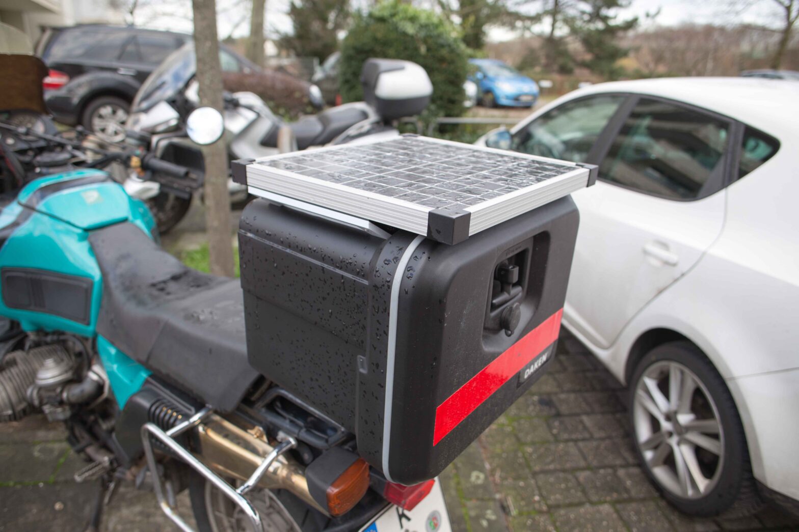
Instead, I had the idea of a top case for the motorcycle luggage rack with a solar cell on top. I wanted to have a motorcycle case anyway so that I could stow my helmet in it and I thought that attaching a solar cell to it would be a simple, cheap and efficient solution. As ready-made motorcycle cases are ridiculously expensive, I decided to use a storage box for the side underride guard on flatbed trucks instead. These are inexpensive, very robust, often used, waterproof and available in many designs. I wanted to install the largest possible solar cell on it. The advantage of the solar cell for me was that although it only has a low charging current, it always charges the battery, regardless of whether I’m driving or not. And to ensure that the battery is always sufficiently charged over time.

I opted for a plastic truck storage box measuring 410x348x340 mm and with a volume of 29 liters. It’s perfect for storing my motorcycle helmet and the solar cell charge controller. At €45, this was a reasonable price for the excellent quality of workmanship. I attached a monocrystalline 20 W solar cell to it using several 3D printed brackets. With a nominal output of 20W, Vmp of 18.4 V and an Imp of 1.09 A, this has sufficient power. With installation dimensions of 370x345x25 mm, it fits exactly on the storage box.
The crate itself is also securely fastened directly to the motorcycle’s luggage rack using several 3D printed brackets. As the box is considered cargo, there are no problems with the German TÜV. The solar cell is mounted in an airy position to ensure good air circulation underneath.


The charge control is simply designed as a PWM version. This does not make it very efficient, but it is robust and very inexpensive. I have installed two DC-DC step-down converters and protected each of them with a diode against reverse currents. One step-down converter is set to a charging voltage of 14.2 V in winter and 13.9 V in summer. The second converter is set to 5 V and ends in a USB-A socket and can be used as a charging point for USB devices.

I have been using this system for several months and have been more than satisfied. It far exceeds my expectations.
List of Material
5 V DC-DC Step-Down Converter
https://amzn.to/3UR1KyM
12 V DC-DC Step-Down Converter
https://amzn.to/3OVNj8V
20 W Solar panel
https://amzn.to/3OVhywz
Storage box
https://amzn.to/49soNnT