
Introduction
Circular, uniform and bright illumination is an essential requirement in stereomicroscopy. Unfortunately, cheap ringlights are either not bright enough or too simple in design. Industrial illumination systems for stereomicroscopes (e.g. SCHOTT, or ZEISS), on the other hand, are ridiculously expensive. So it was up to me to build something of my own.
I have directly excluded ringlights that are constructed as optical waveguides. On the one hand because of the difficulties to build such a system myself, on the other hand because of the lack of necessity. Optical waveguides of this type originate from the pre-LED era with halogen lamps that get hot and emit more infrared radiation than light in the visible range. With modern LEDs, a ringlight can be constructed compactly, efficiently and with minimal heat emission. As already mentioned elsewhere, I prefer to work in the medium possible power range when using a device regularly. This way, you still have a power reserve upwards. For this, I assumed a luminous flux of 1000 lm as a minimum in the first version. Due to the simplicity in terms of cooling and mounting, I wanted to use 5 mm LED.
Design of the Ringlight
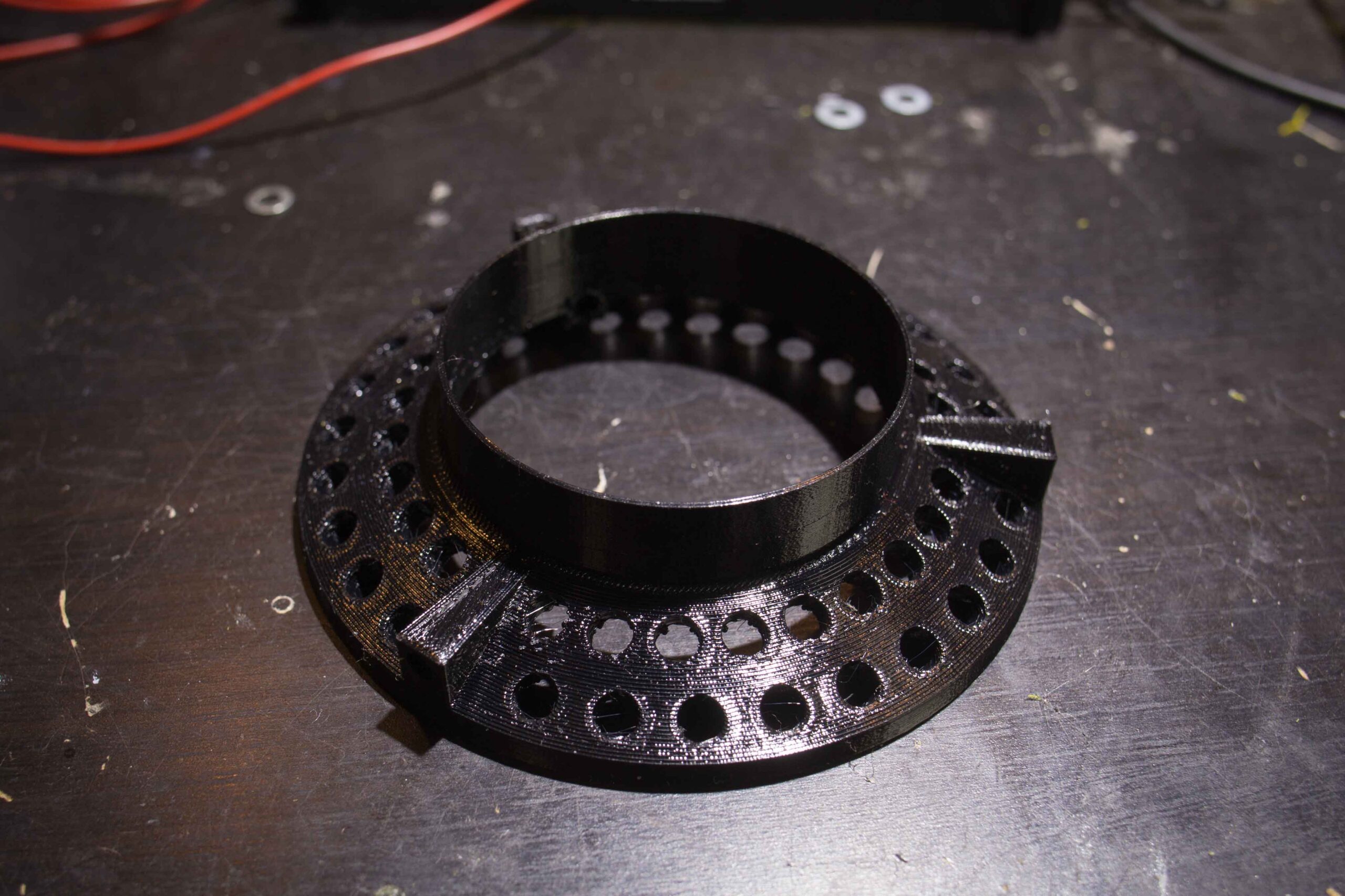
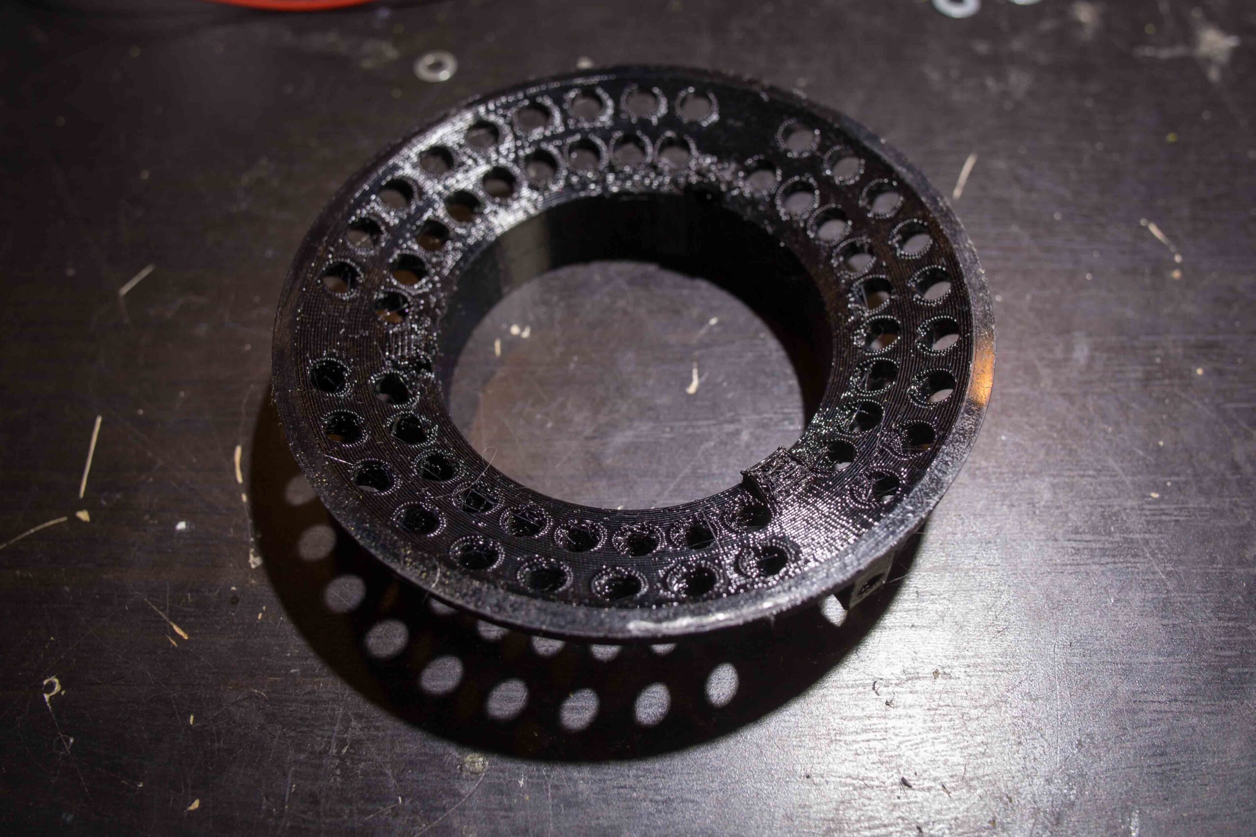
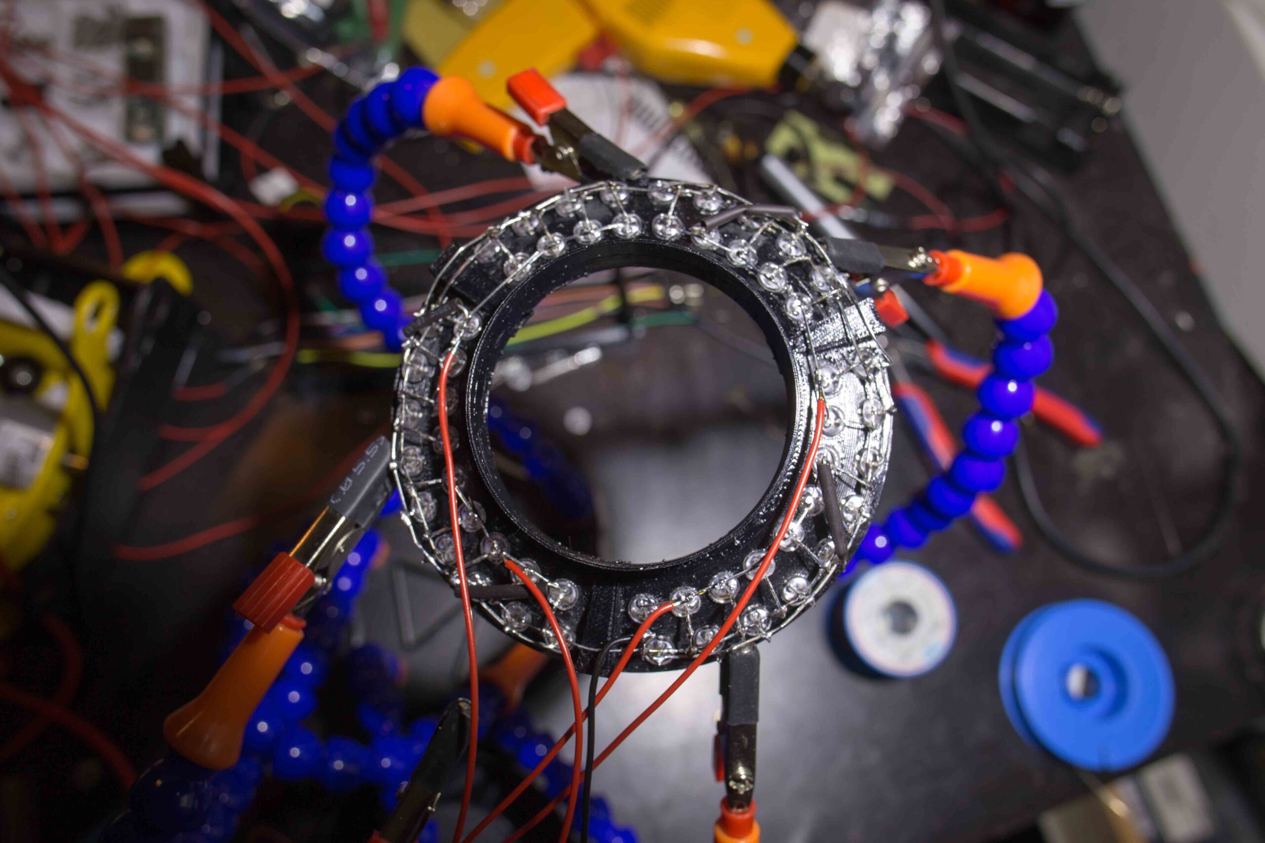
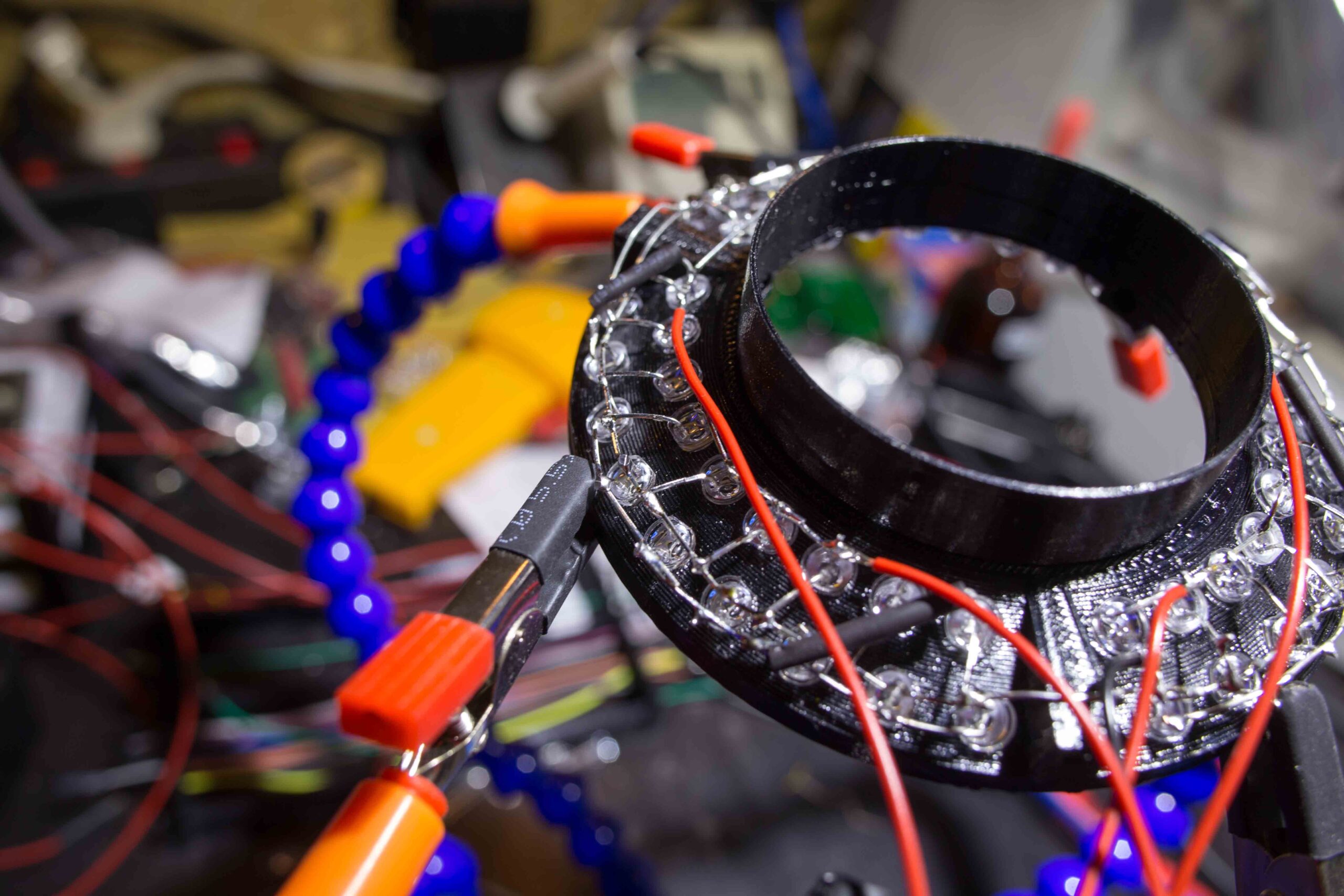
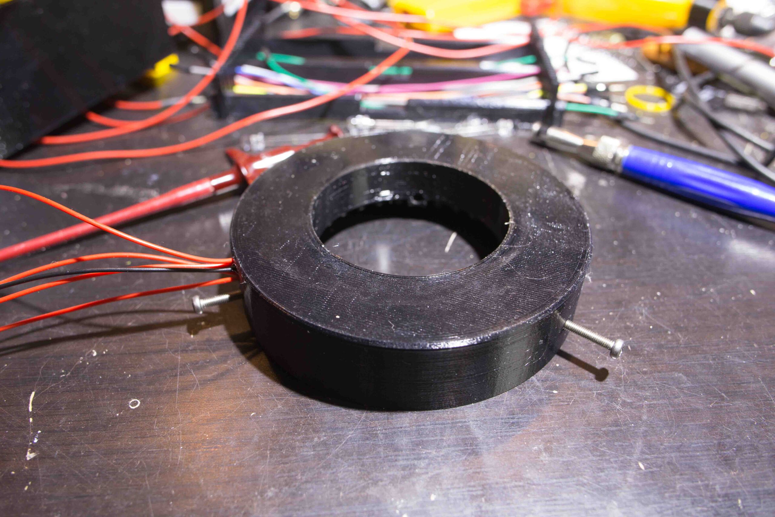
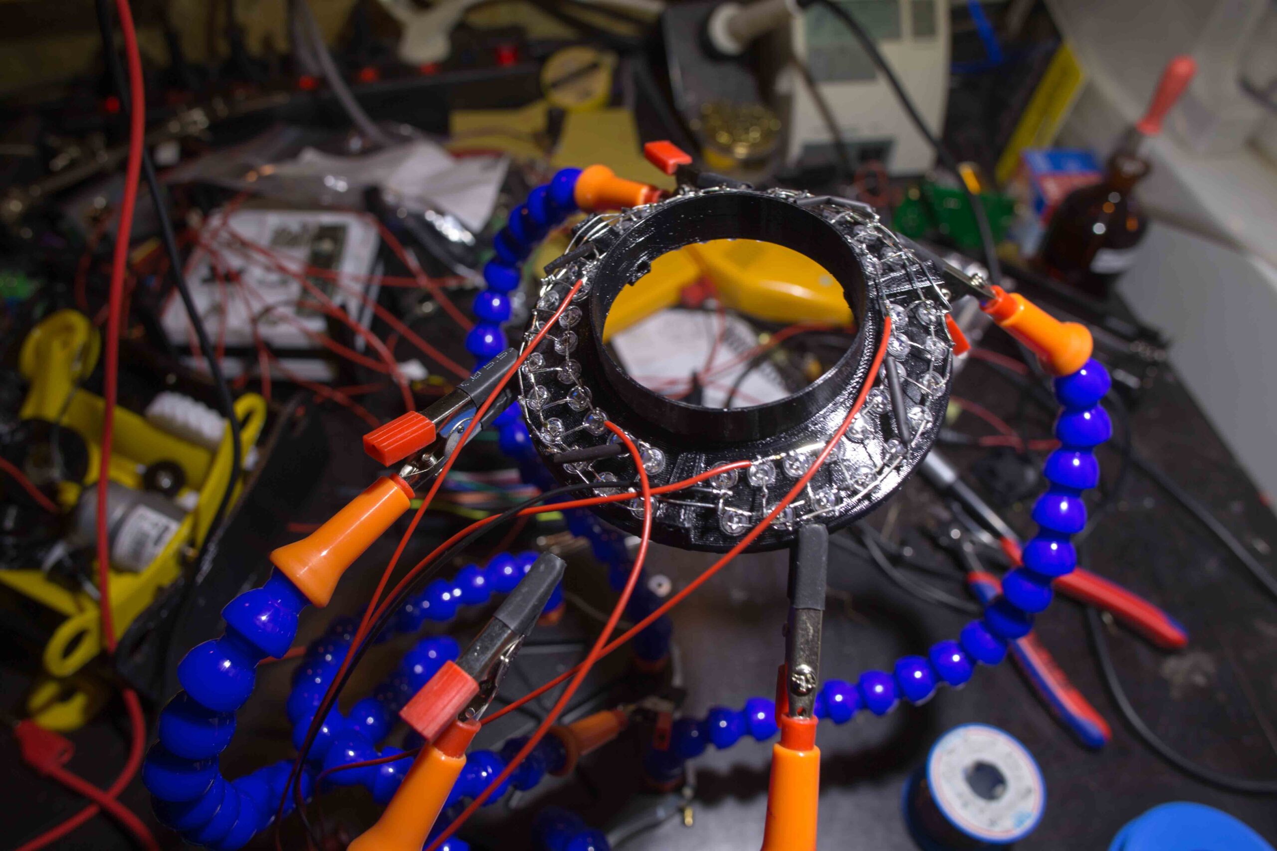
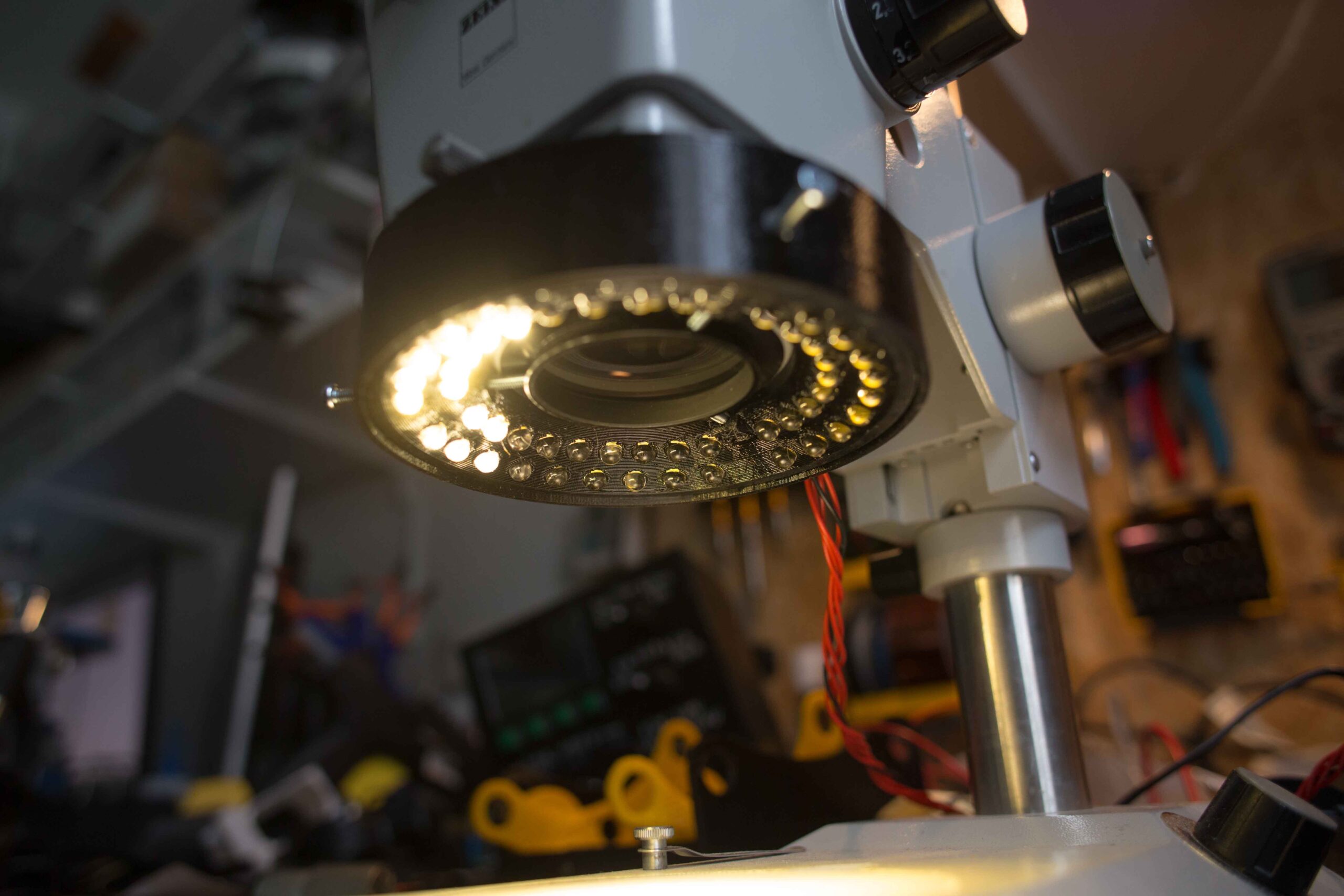
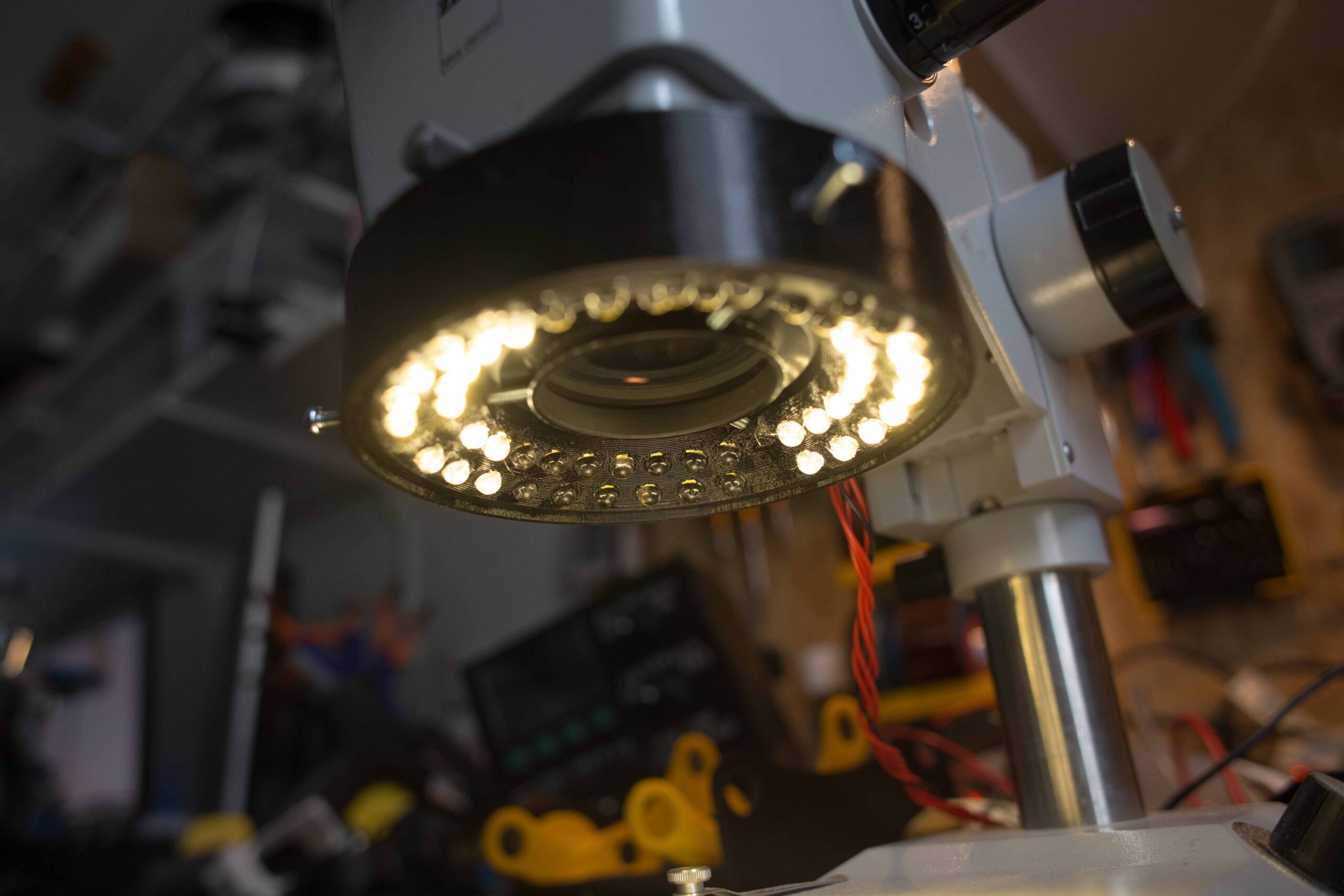
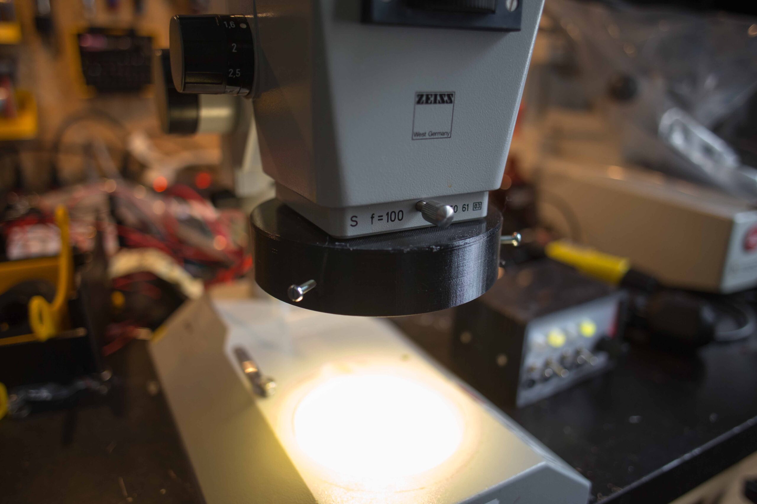
I designed the ring light so that it can be easily attached and adjusted with three screws. The size is as small as possible without complicating the mounting of the LED too much. The diameter is chosen so that the macroscopic view of the object is not obscured. The 5 mm LEDs are aligned in two rows and slightly offset in height. Each individual LED is aligned horizontally and vertically at an exact angle to the center of the field of view. The alignment angle is designed for a working distance (in the focal plane) of 90 mm.
I have provided cable grommets to simplify soldering together. A provided cover closes the ringlight suitably.


Assembly and electronics
The search for very bright 5 mm LED with a good price-performance ratio was not easy. A good overview of 5 mm LEDs from the Japanese company Nichia can be found here, and from Opto Supply here. The luminous flux is composed of the luminous power in candela and the beam angle of the LED. A simple calculator to convert to lumens can be found here. I had shortlisted the following LEDs:
| Name | Max. VF | IF | Luminous Flux | Spectrum |
|---|---|---|---|---|
| Nichia NSPW500GS-K1 (Datasheet) | 3.5 V | 20 mA | 2.37 lm (44 cd @ 15°) |  |
| Nichia NSDW510GS-K1 (Datasheet) | 3.7 V | 70 mA | 25.5 lm (27.5 cd @ 35°) |  |
| Opto Supply OS6MFL5A31A (Datasheet) | 3.6 V | 60 mA | 20 lm (93 cd @ 30°) | n/a |
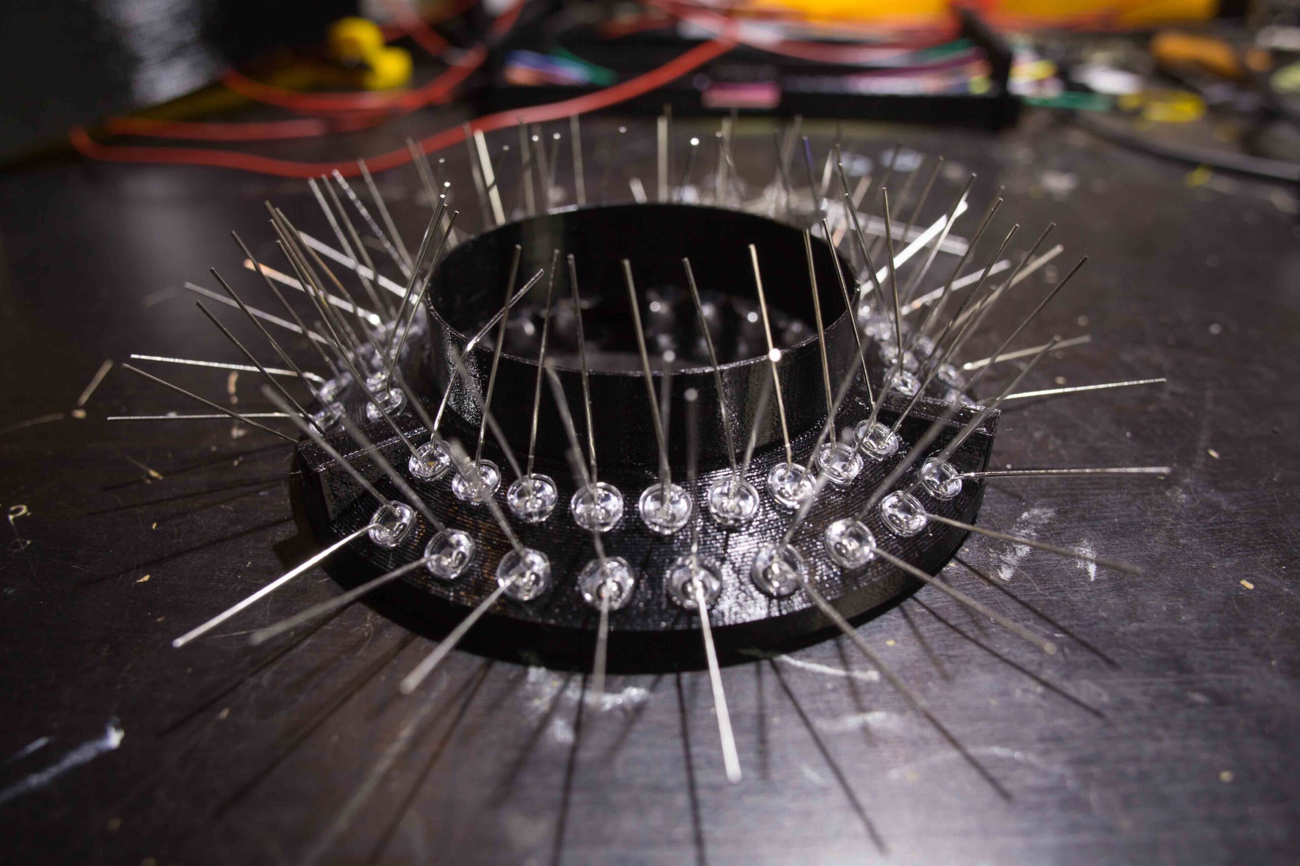
I chose the LED Opto Supply OS6MFL5A31A because of its high brightness and low price 0,23 €. With 54 LEDs installed, this means (with parallel connection) a voltage of 3.6 V, 3.24 A (11.66 W) and a luminous flux of 1080 lm.
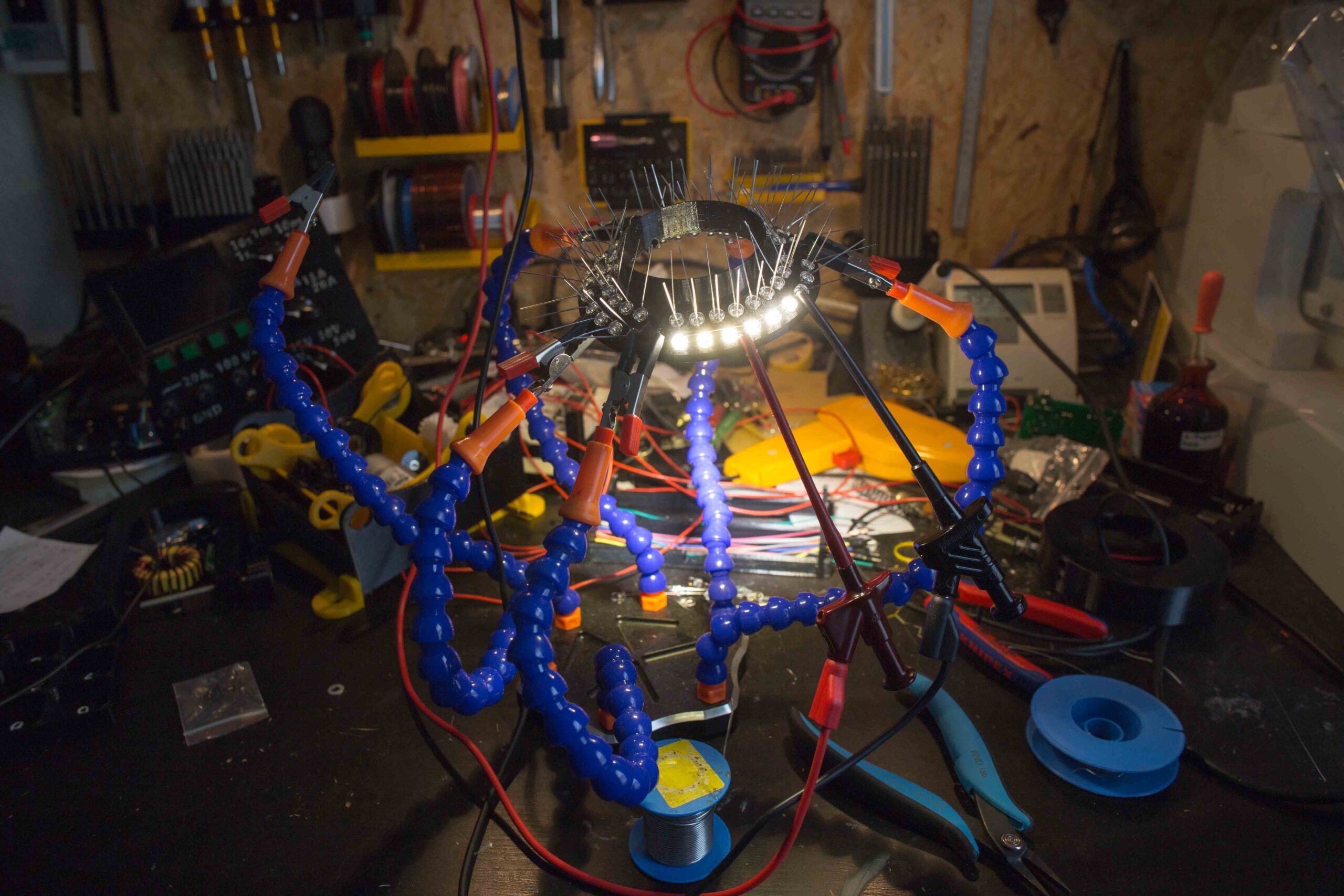
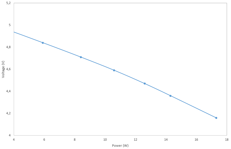
I used a simple 5 V, 4 A (20 W) plug-in power supply from Quad Power as the voltage source and regulated the operating voltage using an XL4015 step-down converter with current limiting. Most power supplies are insufficiently stabilized or the internal resistance of the cable is very high due to a cable cross-section that is too small and the voltage drops quickly under load (Fig 3). Therefore, when buying a power supply, make sure that it has a sufficient power reserve. The XL4015 step-down converter is described with a maximum current of 5 A. This is possible, but requires appropriate cooling! For dimming the LEDs I installed a simple 5 A PWM module in front of the step-down converter. The control range is between 1 and 100 % at a frequency of 10 kHz. This allows flicker-free operation. I have wired the LEDs in such a way that they can be switched to four quadrants, each individually but all together dimmed. This allows a one-sided and oblique illumination of the sample to be able to improve the contrast by targeted shadow casting.

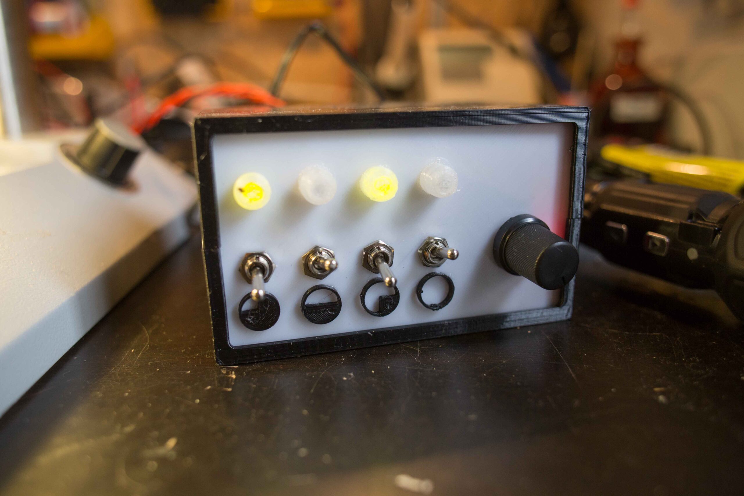
The electronics for control and power supply are placed in a 3D printed box, which I created with the help of the OpenSCAD customizer “The Ultimate box maker” of the Thingiverse user “Heartman“. I have adapted my version to the needs of the ringlight and also made it available as a remix for download at Thingiverse.


Results
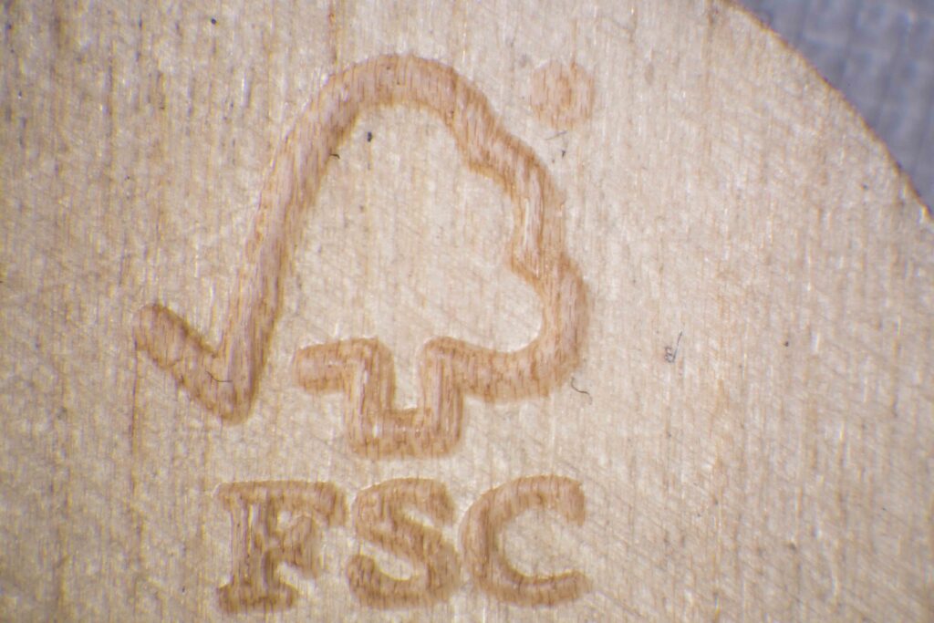
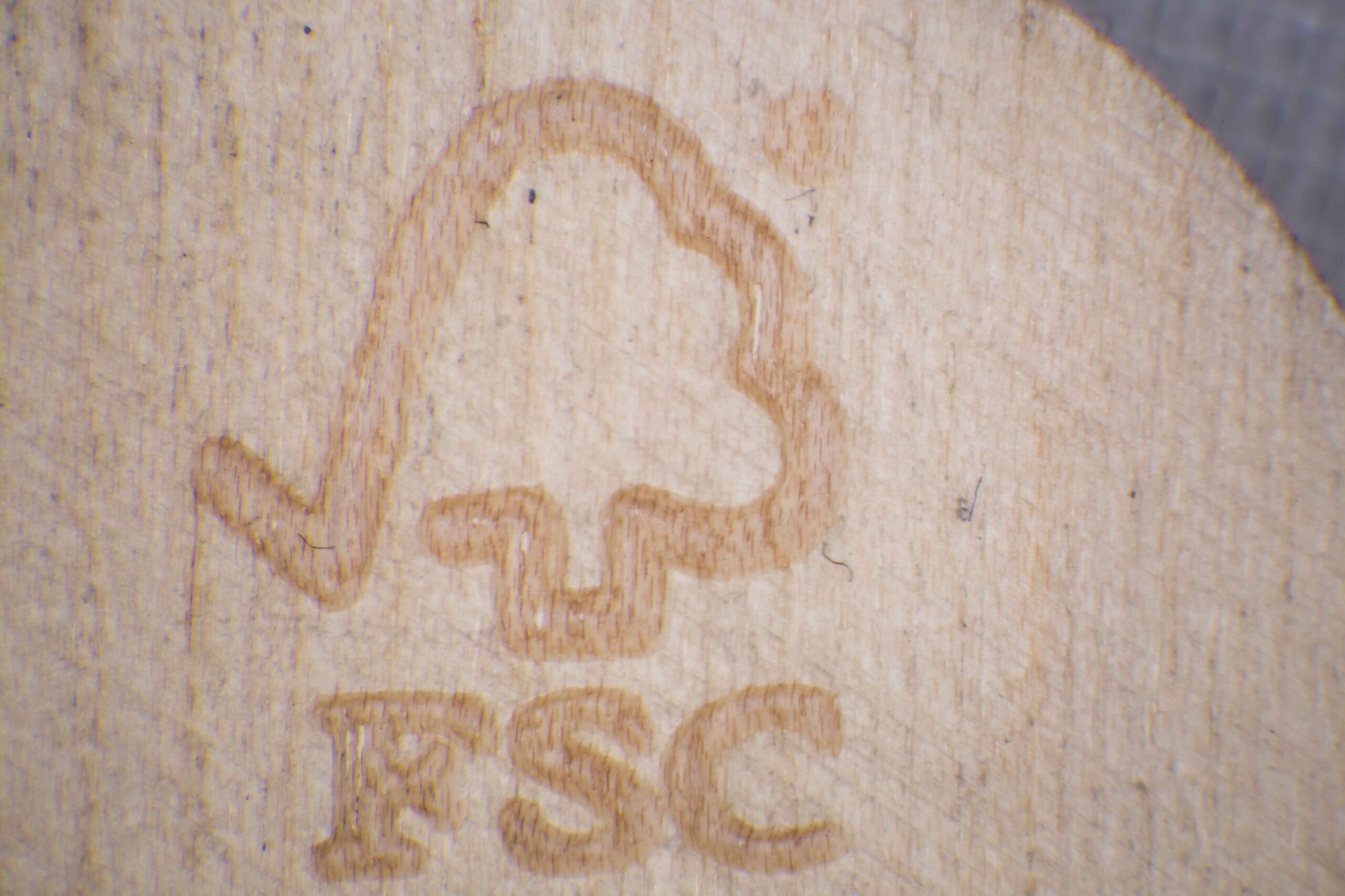
With the same camera settings and exposure time, a direct comparison with the old ring light shows a clear improvement in terms of brightness and illumination (Fig 4). The warm white color temperature of the LEDs is not optimal, but should not disturb during use.

Old ringlight 
New ringlight with same camera setting

The assembly worked well and was trouble-free. There is no flickering during operation due to the pulse width modulation and the voltage and power supply seem to be selected appropriately. The selective switching on of individual quadrants leads to a significant improvement in contrast (Fig 5). Due to the free selectability of the quadrant, the specimen does not have to be rotated.
Skewed lighting with one quadrant switched on 
Full ring lighting

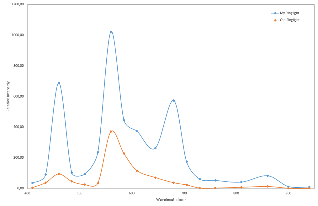
The spectral analysis (Fig 6) shows a clear peak at 680 nm which is responsible for the warm white color of the LED. The measurement data were recorded with my self-built spectrometer (I will present it in another article). Averaging the relative intensity over the whole measurement spectrum of both ringlights results in a value of 242.19 for my device and 62.30 for the old one. This corresponds to a factor of 3.9.
Material